The Zephyr Project is a highly configurable and flexibile RTOS for embedded devices that supports a growing range of architectures and a huge collection of development platforms. Possibly one of the most interesting features of the Zephyr code base is the ability to almost seamlessly port code from one architecture to another using the devicetree and board definition model for hardware description along with its powerful device driver interfaces. However, with such a powerful set of platform abstraction features comes with it a dense and complex build and configuration system.
Zephyr uses a combintation of CMake for build configuration, Ninja or Make for building, and Kconfig to set configuraitons for libaries, architectures, boards and their dependencies. To unify these tools and provide a simple interface to the build, flash and debug process for all compatible platforms and toolchains, the project includes a tool called west and is so-called a swiss-army knife CLI tool. In addition to building, flashing, and debugging, west allows the management of multiple repositories
Out-of-Tree Modules
I like to keep project workspaces and the main Zephyr source tree separate. This is a convenient way to isolate your own code/drivers that aren’t necessarily destined for the main Zephyr project repository. For code that is being written for my own projects and is likely to be reused/ shared between multiple projects (e.g. device drivers), creating out-of-tree modules is a useful way to put together repositories of somewhat related library code In this post, we will look at a straightforward method to create an out-of-tree (OOT) module for storing some platform-independent or otherwise portable code that might be used for multiple projects. This can be treated like a tutorial but the easiest way to get started is to clone the companion git repository created for the post.
Getting Started
To keep it brief, we will only cover the absolutely necessary aspects required for creating a usable OOT module. Following this we’ll add in a very simple driver to demonstrate where you might go once you have a skeleton module structure that can be included in a Zephyr app.
As this article is not supposed to be an introduction to Zephyr or a tutorial on how to setup your environment and build system, we will make a couple of important assumptions:
- You have a functioning Zephyr build system for your desired targets and are comfortable creating board overlays for your target architecture.
- You have an existing Zephyr app with some driver/library code which you would
like to break out into a module (already having library/driver code is not essential).
OR
You can use the project we created in a previous post which we use to demonstrate the use of the OOT module. The git repo can be found here - You are comfortable using west to build and flash Zephyr RTOS binaries to your target architecture. With that out of the way, we can start looking at setting up an OOT module.
Directory Struture
There are a few basic requirements in terms of files and directory structure that need to be present in order to build an out-of-tree module and work with the sometimes seemingly complex build system that Zephyr uses (a combination of West, CMake, and Kconfig). In this post we will consider that our OOT module contains a single sensor driver that can conforms to the Zephyr project sensor driver interface. Luckily it is relatively simple to put together this barebones structure and it should look like the below:
my_oot_module
  |-- drivers
  |-- dts
  |-- include
  |-- zephyr
        |-- module.yml
  |-- Kconfig
  |-- CMakeLists.txt
Note: it goes without saying that this directory should be located somewhere else in your filesystem from the main Zephyr source tree.
We start with the base directory that will hold our module, my_oot_module. Inside
that we need:
- A directory named
drivers - A directory named
dts - A directory named
include - A directory,
zephyr, with amodule.ymlfile inside it. - A
Kconfigfile CMakeLists.txt
As might be self-explanatory, the folders drivers, dts, and include follow a
similar structure to the way they appear in the zephyr project source tree, which
we try to replicate in our OOT module for consistency. These folders will
hold the necessary code, definitions, and public interfaces for our sensor driver.
The zephyr directory holds a single file, module.yml that links our module
to the zephyr source tree by way of a module
in the context of the Zephyr documentation. Without going into too much detail,
parts of the Zephyr project source are modules in the sense that they are externally
maintained projects integrated into the build system. The key point being that
they aren’t directly part of the main Zephyr repository - similar to how we want
our OOT module to exist alongside our main Zephyr repo.
The contents of our module.yml is as follows:
|
|
Lastly, we can discuss the two files which we will become painfully familiar with that take care of Zephyr’s build system.
Kconfig:
Zephyr uses Kconfig for build time configuration which can be modified by both an interactive interface and editing the symbols inside flat Kconfig files themselves. In our base Kconfig file we will only setup our module’s interactive configuration menu option and point to the other configurations. It should look something like this:
|
|
CMakeLists.txt:
Zephyr also uses CMake to build both the kernel itself and any application you’re developing
CMake
via CMakeLists.txt scripts littered throughout the main repo and your own modules/projects.
Inside CMakeLists.txt, we add a few lines to add our module’s include directory to the zephyr include directories
and add the drivers directory as a subdirectory. This drivers directory will house our actual library code.
|
|
Giving our module purpose
From here, we can start adding in our actual folders to house library code. In this post we’re going to use the driver for an IC2 ambient light sensor from Rohm Semiconductor, the BH1750FVI which is basically obsolete but still easily available from Mouser/Digikey and on breakout modules. We will only focus on the overall structure of the driver in the context of an OOT module without going into the part-specific aspects. This will help to demonstrate the certain conventions within the Zephyr framework and requirements for OOT modules. Furthermore, as this is a sensor driver we will also be able to see how our OOT module can easily integrate into the existing sensor driver interface provided by Zephyr.
  my_oot_module
  |-- drivers
        |-- sensor
              |-- bh1750
                    |-- bh1750.c
                    |-- bh1750.h
                    |-- CMakeLists.txt
                    |-- KConfig
              |-- CMakeLists.txt
              |-- Kconfig
        |-- CMakeLists.txt
        |-- Kconfig
  |-- dts
        |-- bindings
              |-- sensor
                    |-- rohm,bh1750-i2c.yaml
  |-- include
        |-- drivers
  |-- Kconfig
  |-- CMakeLists.txt
  |-- zephyr
        |-- module.yml
As you can see, we have now added a whole lot of files and folders to the barebones
module structure that is really a lot of boilerplate build system stuff to get
Zephyr to build our module. Notice under the drivers folder we have created
a sensors folder and placed inside that another folder that is the name of
our actual driver; this is for clarity and to mimick how the main Zephyr source tree
organises sensor drivers. It means you can then include your own OOT driver just like you would
for an in-tree Zephyr-provided one.
You will also need the requisite CMakeLists.txt and Kconfig files in each of these new directory levels
and the content of each will contain at least the following:
# drivers/CMakeLists.txt:
# -----------------------
      add_subdirectory_ifdef(CONFIG_SENSOR sensor)

# drivers/Kconfig:
# -----------------------
      rsource "sensor/Kconfig"

# drivers/sensor/CMakeLists.txt:
# -----------------------
      add_subdirectory_ifdef(CONFIG_BH1750 bh1750)


# drivers/sensor/Kconfig:
# -----------------------
      rsource "bh1750/Kconfig"

# drivers/sensor/bh1750/CMakeLists.txt:
# -----------------------
      zephyr_library()
      zephyr_library_sources(bh1750.c)


# drivers/sensor/bh1750/Kconfig:
# -----------------------
      config BH1750
	        bool "Enable support for the BH1750 driver"

      config BH1750_MODE_CONT
            bool "continuous measurement mode"

      config BH1750_MODE_SINGLE
            bool "single measurement mode"

      config BH1750_0_5lx_RES
            bool "0.5lx resolution measurements"

      config BH1750_1lx_RES
            bool "1lx resolution measurements"

      config BH1750_4lx_RES
            bool "4lx resolution measurements"
The final addition to our directory structure are the device tree binding for our BH1750 sensor driver. The Zephyr framework documentation has an extremely thorough write-up on the use of Devicetree (DT) bindings in the Devicetree Guide so the interested reader should head there to learn more or accept what we do here for the time being. Because our sensor is a straight-up I2C device without any extra IO to interface with, our bindings file can take advantage of the i2c-device bindings provided by the Zephyr framework. Thus our DT bindings file for the Rohm BH1750 will look like the following:
|
|
It is important here to take note of the naming conventions for this file as it is must adhere to the naming conventions for compatibles within DT nodes. Once again, we refer back to the Devicetree Guide with which you should be familiar with before implementing your own driver. The key takeaway here is how the folder structure from dts downwards. This is because the build system is going to look for bindings in dts/bindings subdirectories. And, as we have specified the dts_root parameter as “.” in our module.yml file our directory structure must conform to this requirement.
Library code
Going over the library code for the BH1750 driver might be interesting but is way out of scope for this post. So we will skip over the details and assume that you’ve cloned the Github repo that is a companion to this post and are following along.
The driver implementation allows the core functionality of the chip to be used in both single-shot and continuous conversion modes. It also supports configuring the device in 0.5, 1 or 4 lux resolution modes. See the datasheet for more.
Using the module
Now, we’re at the point where we can actually use this driver inside our OOT module. To demonstrate it we will need an application that will include our module along with the rest of the kernel and build them together into one binary. While it would be cool to write up how to create a project (Zephyr application), the main Zephyr project documentation details this throughouly enough that it would be a largely pointless exercise. See here for the relevant documentation page.
If you dont want or need to spend the time creating your own, I’ve created a repo that serves as a starting point or template to create new barebones Zephyr apps which can be found here. We will use this as a starting point and explain the process of using our OOT module as if we just created a new application. Eventually, we will end up with a full but simple example that uses the module and its one driver and the complete repo for that is here.
Setting up
Firstly, we need some hardware, and for that we will be using an STM32 Nucleo-64 board (with an STM32L476RG). Conveniently, Zephyr already has the required board definition for this dev board which is called nucleo_l476rgs. We are also using a cheap BH1750 light sensor module that often goes by the name GY-302 on eBay or Aliexpress. I got mine here.
To let Zephyr know that we have a piece of hardware connected to a set of pins and a specific peripheral on our MCU, we need to create a board overlay file that assigns things such as the I2C peripheral number, slave address, and the compatible name which matches the appropriate device tree bindings for our device. This board overlay should be contained in a “boards” directory in the project root and is a devicetree file named “<board_name>.overlay”. Thus, we will have a board overlay called “nucleo_l476rg.overlay” in a “boards” directory that contains something like the following:
|
|
What this does firstly is set the clock frequency of the i2c1 peripheral defined for our board to the standard 100kHz bitrate. It defines the bh1750 device, specifies its slave address as 0x5C using the reg parameter, and also sets the compatible name to that of the correct device driver. Recall that we created a DT bindings file for this same compatible inside our OOT module earlier.
Now we’ve told the build system where and how our device is connected, we need to actually do this with some hardware. As we’ve selected i2c1 as the I2C interface to which our sensor is connected, we need to find out which pins on the board have been assigned to the corresponding SCL and SDA signals. This is easily found in the main board definition file for our board and because its part of the main source tree we need to do a bit of digging to find it. Fortunately, it’s not that hard and our NUCLEO-L476RG board definition can be found at “zephyr/boards/arm/nucleo_l476rg/nucleo_l476rg.dts” in the zephyr project source. Scrolling through that file we will eventually find a definition like so:
|
|
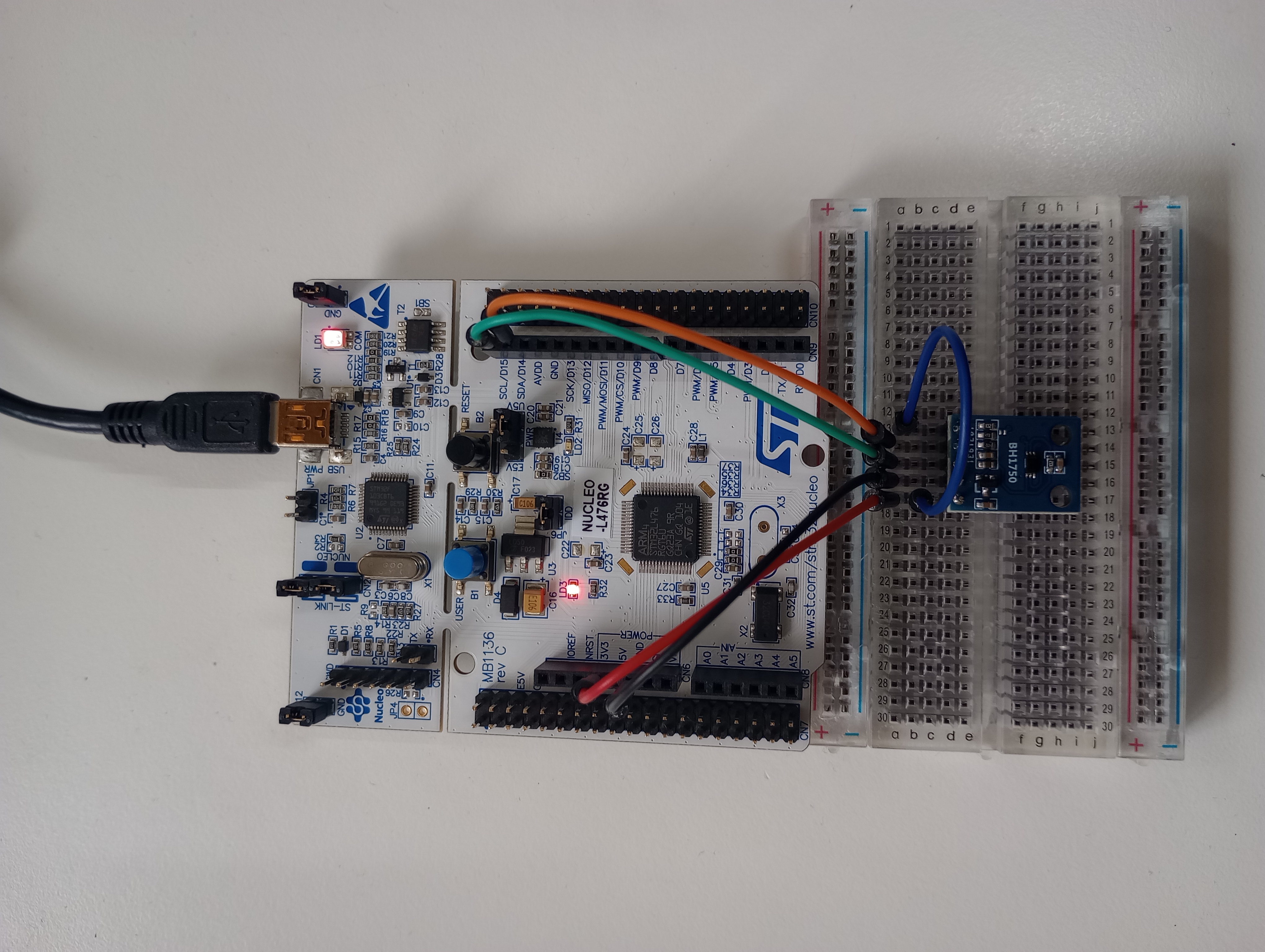
The pinctrl bindings make it pretty clear how the IO multiplexing for this MCU is set up on this board. We can see in the listing above that our SCL pin is connected through PB8 and SDA through PB9. With the pinout of the dev board itself (shown below), now we know where to wire up our device.

With a breadboard and a few jumper wires we can now hopefully wire up our sensor module correctly. Note that we are also pulling the ADDR pin of the BH1750 chip high to make sure it’s I2C address is 0x5C and that the module already has pullup resistors on the I2C lines and thus we haven’t added any.
Using the BH1750 driver
Back to our project, we can finally start writing some code that actually gets Zephyr RTOS up and running along with an I2C driver and our BH1750 driver. Being an incredibly simple sample there really isn’t much in the way of actual code for our app (not counting the driver/OOT module) and as such we have a single source file named main.c. Let’s break it down into three parts. First up we have the necessary includes:
|
|
For our app, we need only the main zephyr.h header and the sensor.h driver interface. Zephyr’s sensor subsystem provides a neat uniform API to access any sensor device drivers through. It means that the underlying drivers can be as complex or as simple as needed without exposing this to the application. See here for the official documentation on the sensor API.
Next we define a function to get a usable instance of our sensor device, returning it as a struct device with which you are or will soon be innately familiar.
|
|
This function basically just uses a Devicetree helper macro DEVICE_DT_GET_ANY() to find any device we have specified for our board (think our board overlay file) with the compatible that matches “rohm_bh1750” and returns it as a Zephyr device instance.
The last part of our source file is the main function where our app starts and enters it’s never-ending loop. Ignoring all the print messages, we start by using that handy get_bh1750_device() function to get a pointer to the sensor device driver. If that was successful, we continue on into the infinite loop, trigger the sensor driver to fetch a sample, get that sample from the light channel, and finally print it out so we can see what the device read.
|
|
Ideally, we would be checking that sensor_sample_fetch() and sensor_channel_get() didn’t return errors but for the sake of a simple example we don’t.
Now that we actually have a project configured to use our OOT module, some hardware set up, and some code to test out that hardware and driver inside the OOT module, we’re finally ready to build and run…
Testing it all out
We will use the west tool to both build and flash to our board along with a
serial terminal to view the output to the Zephyr console (which appears as a virtual COM
port when our board is connected via USB).
With the Nucleo-64 board we are able to build our app for the first time by running:
west build -b nucleo_l476rg
in the project directory (we can ommit the -b switch and board name to avoid rebuilding every time).
Our app is successfully built and we now have a binary:

Finally, while the board is connected we can then run west flash to get
that binary onto the hardware!
After doing that and opening up a terminal, connecting to the Nucleo-64’s virtual COM port for the Zephyr console output, we get something like the following as the board is reset, Zephyr boots, and our app starts:
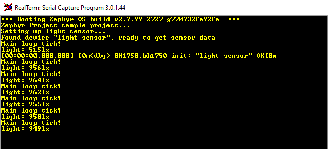
You can see that we get a debug message from the BH1750 driver that we initialized OK and the app immediately starts reading back value from the sensor. A final sanity check with the sensor covered and uncovered with a piece of cardboard shows that we are definitely seeing real data and have a working chip:

Conclusion
At this point we have now created our OOT module, placed some driver code and interfaces inside it, and created a sample app which builds the module alongside the rest of the Zephyr kernel. Hopefully we also have a solid understanding of both the structure of and process for setting up and building drivers and subsystems from custom OOT modules.